Executive Summary
- Deltaweld® 652 constant voltage MIG welders provides the duty cycle ITEC requires and offers the ability to optimize arc starts by manually changing the machine’s open circuit voltage.
- Miller’s Swingarc™ boom-mounted 70 Series constant speed wire feeders, with its 16-ft. boom, increases an operator’s work envelope and it reduces cable clutter on the floor.
- Hobart Brothers Tri-Mark flux cored and metal cored wires are used for their excellent tensile strength in cold weather.
- Bernard’s 600 amp Q™-Gun (with patented Jump Liners) and Centerfire™ consumables requires no tools to replace the tip or nozzle, and features a “drop-in” contact tip with no threads for quick and easy changeover.
Equipment Selection, Organization Creates Maximum Throughput For Utah-based Company
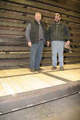 |
Fig. 1: ITEC plant manager, Rodney Keller (left), and plant foreman, Mike Grimes, stand proudly on top of these finished rigmats, which are destined for the Canadian oilfield
|
The Muskeg—a swampy concoction of peat and rotting plant life—has plagued the Canadian oil drilling industry for years. Yet underneath the deep layers of muck and decay lay vast deposits of the world’s most demanded natural resource. Oil mavericks were finally able to access these oil deposits with the introduction of rigmats: large planks of wood and steel used to build roads and drilling platforms that disperse the weight of trucks and drilling rigs and prevent them from sinking into the bog.
In early 2006, Canadian oil companies approached ITEC Manufacturing, USA of Brigham City, Utah to mass-produce these rigmats. ITEC CEO Bart Penrod is world-renowned for his manufacturing prowess and has worked on such high profile projects as the space shuttle redesign. Penrod also contributed to the advancement of the Theory of Constraints—a methodology now taught at universities worldwide—while attending the Avraham Y. Goldratt Institute.
Penrod and plant manager Rodney Keller set up a new manufacturing facility in Ogden, Utah with the goal of producing 96 rigmats per day. ITEC achieved this goal within three months by working with representatives of Miller Electric Mfg. Co, Hobart Brothers and Bernard® to outfit the facility with a fully integrated MIG welding system and consumables that could optimize the flow of production.
“The rigmat market is pretty much unlimited for us right now,” reports Keller. “Because of the techniques we use, we’re able to produce them quicker than most of the companies that have been doing it for a long time.”
Manufacturing and Set-Up
ITEC constructs its rigmats with three 40-foot long, W6x15 I-beams running parallel to each other and connects each of these I-beams by six cross members that run perpendicular to the main beams. Fabricators box off each beam with 1/4-in. sheet steel that, when stitch welded in place, make the rigmats look like a pontoon (see Fig. 1). The entire frame is constructed of A36 mild steel and features eye-hooks at four steel cross-member pick points to allow for easy extraction from the muskeg. Six-by-six wood planks are placed into the center and the frame and are custom coped to fit the beams. Once everything is butted together, the entire frame is welded up and the rigmat is complete.
To achieve the production rate of 96 rigmats per day, optimize flow and minimize downtime, ITEC had to address several manufacturing and quality challenges:
- Choose a MIG welder that would provide the desired output (650 amps at 100 percent duty cycle).
- Choose a welder that would allow ITEC to tailor the arc start to its application.
- Give welders easy access to wire feeders at either end of the 40-foot platforms.
- Use wire feeders that are easy to adjust and provide a consistent feed.
- Choose welding wire(s) with the appropriate cold and tensile strengths, and the ability to weld in all positions.
- Use consumables that last longer and require minimal downtime to change.
Optimized Arc Starts
 |
|
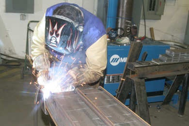
Fig. 2: ITEC welding fabricator, Cory Francis, who is using a Deltaweld 652 to box in this I-beam, reports that the Deltaweld 652 has smooth arc starts¾and he’ll make approximately 160 arc starts to box in this beam.
|
After examining the company’s power source and wire feeder needs, ITEC outfitted the new facility with 20 Deltaweld® 652 constant voltage MIG welders (see Fig. 2), many of them paired with 70 Series wire feeders with digital displays and mounted on Swingarc™ wire feeder booms (see Fig. 3). Miller Electric manufactures each of these products, and each piece of equipment offers benefits that allow ITEC to streamline production.
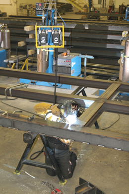 |
Fig. 3: ITEC line foreman, Jeff Kotter, shown here welding, reports “The Swingarc-mounted feeders eliminate tangled cords in the work area. A clutter-free work area helps us accomplish our goal of high-productivity welding because we don’t have to stop and untangle cords.”
|
While the Deltaweld provides the duty cycle ITEC requires, the greatest benefit is the ability to optimize arc starts by manually changing the machine’s open circuit voltage. “The new technology on the Deltaweld controls the arc so well,” says Keller. “We can control our starting amperage and starting open circuit voltage so that we’re not getting burnback and burning our tips up.”
The machine comes preset at 30 volts, but ITEC has increased this setting to 32 volts. The higher open circuit voltage provides a smoother arc start and ensures that the filler wire is melted by the time it hits the base metal. If the filler wire is driven into the weldment before being completely melted, it can create cat whiskers and/or burnback into the tip. Such discontinuities can lead to costly downtime for weld repairs or changing contact tips.
“My grandpa always told me, ‘If you don’t have time to do it right the first time, when are you going to find time to fix it?’ And because we’re producing 96 rigmats per day, we don’t have any time for rework,” says Keller.
Keller and his crew have also found that the Deltawelds draw less power than welders they have used in the past.
“I put a Deltaweld out here,” reports Mike Grimes, plant foreman, ITEC, “and they were stitch welding [boxing in the I-beams] with .052-in. wire at 30 volts and 355 inches per minute (IPM) of wire feed speed, and we were pulling less than 20 amps of primary power.”
In addition to the low amperage draw, the Deltaweld has impressed operators with its ability to conserve energy through its Fan-On-Demand™ feature, which only turns the cooling fan on when needed and minimizes the amount of potentially corrosive airborne contaminants being pulled into the machine.
“The fans hardly ever kick on, and that means the machines are not being overworked,” says Cory Francis, welder, ITEC. “They’re not drawing too many amps, and they’re not heating up.”
Digital Feeder Consistency
Stationed next to each power source are Miller Electric’s Swingarc boom-mounted 70 Series constant speed wire feeders. The Swingarc design, with its 16-ft. boom, increases an operator’s work envelope (see Fig. 4) and it reduces cable clutter on the floor.
 |
|
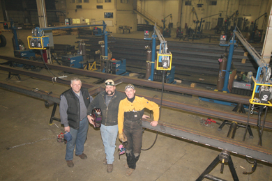
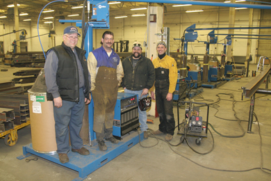
Fig. 4: Note the huge work area covered by the Swingarc-mounted 70 Series wire feeders. Shown (L-R) are ITEC plant manager, Rodney Keller; plant foreman, Mike Grimes; and line foreman, Jeff Kotter.
|
“When we weld a 40-ft. rigmat,” says Keller, “we put a fabricator on each end. One guy can swing in 40 feet (including the 15 foot welding gun/liner) and overlap another guy without having to move a machine. Miller improved these Swingarcs over the old models, which needed to be cranked up to get it to the right height. These are spring-loaded so simply raise up or down.”
However, the most important benefit provided by the 70 Series wire feeders is the ability to set the welding parameters digitally. Doing so ensures repeatability and consistency from station-to-station and simplifies setting parameters.
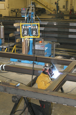 |
Fig. 5: The digital readout on the Deltaweld 652 and 70 Series feeders enable the welding fabricators to set voltage and wire feed speed parameters easily and accurately.
|
“With analog meters, you have one person saying ‘this is set right,’ but then you grab it and it’s set 15 or 20 amps colder than what you’re used to,” says Keller. “With a digital read-out, the settings are right every time. To obtain consistent weld quality, we want every operator using the same voltage and wire feed speed parameters every time they make a weld” (see Fig. 5).
Tri-Mark for Mechanical Properties
Sitting next to each Swingarc in ITEC’s plant are 600-lb. drums of welding wire (see Fig. 6). This amount may sound excessive, but Keller points out that ITEC only uses two wires in this application and that buying in bulk lowers purchase costs, reduces downtime associated with changing spools and actually provides a cleaner feed because the wire is shielded in a drum rather than exposed to dust and contaminants in the air.
 |
|
Fig. 6: To eliminate changeover time associated with 60-lb. spools and to improve feeding, ITEC selected Tri-Mark tubular wire in 600-lb. drums. Shown here (L-R) are ITEC plant manager, Rodney Keller; plant foreman, Mike Grimes; welding fabricator, Cory Francis; and line foreman, Jeff Kotter.
|
ITEC uses two wires: Hobart Brothers’ Tri-Mark .045-in. TM-770 flux cored wire is used for overhead and out-of-position welding, while Tri-Mark .045- and .052-in. Metalloy® 76 metal cored is used for welding in the flat, horizontal or moderately downhill positions.
“We chose Hobart Brothers’ Tri-Mark wires because they provide good tensile strength in cold weather,” says Keller, “and we need to create welds that won’t shatter when heavy pipeline equipment drives over them in the middle of the Canadian winter. Regular solid wire can shatter at subzero temperatures, but not Tri-Mark tubular wire.”
The TM-770 (an AWS E71T-1M and E71T-12MJ H8) flux cored wire features a Charpy V-Notch (CVN) toughness of 90 ft-lbs. at -40 degrees Fahrenheit. The Metalloy 76 metal cored wire (AWS E70C-6M H4) features a CVN toughness of 34 ft.-lbs. at -40 degrees Fahrenheit. These qualities form strong welds in even the coldest temperatures.
Both wires use 85 percent Argon/15 percent CO2 shielding gas. To further streamline their welding processes, ITEC has a bulk supply gas system on most welding stations, eliminating the time associated with cylinder change over and management.
Keller also reports that training welders to run Metalloy wire has been easy. “The Metalloy 76 metal cored wire enables operators to hold a shorter stick-out,” he says. “It’s a lot like spray transfer welding with solid wire, so we can put a moderately experienced welder on it, give him a little bit of training and he can produce an impurity-free weld that meets AWS D1.1 standards.”
One key piece of advice Keller gives: use the push, or forehand, technique when using metal cored wire like the Metalloy 76. “You cannot use the pull technique with metal cored wire and get a good weld because impurities tend to become trapped in the weld puddle,” he says. “Conversely, using the push technique enhances the cleaning action, and it provides better penetration.”
Tips and Jump Liners
ITEC’s welding system features Bernard’s 600 amp Q™-Gun (with patented Jump Liners) and Centerfire™ consumables. When choosing this set-up, Keller wanted to avoid the usual downtime associated with changing tips, nozzles and liners.
Bernard’s Centerfire design requires no tools to replace the tip or nozzle and features a “drop-in” contact tip with no threads for quick and easy changeover. A large diameter tip base and tapered seat provides improved electrical conductivity and heat transfer, and a spatter shield within the nozzle helps ensure smooth gas flow.
"It was really fun to watch people when they first had to change a contact tip (with the new Centerfire consumables),” says Keller. “Our welders would pull it off and say ‘it’s broken! It doesn’t have any threads, how am I going to fix it?’ I said ‘just pull it out and put the other one in.’”
Another source of savings has been Bernard’s Jump Liners. Liners typically wear out at a friction point created by the bend of the MIG gun’s neck and need to be replaced to prevent poor wire feed. Instead of requiring ITEC to replace the entire liner, Jump Liners allow welders to replace just the area that has been worn—a feature that has added up to a substantial savings in cost and time.
“A Jump Liner can be changed in under a minute,” says Grimes. “A regular liner could take 15 to 20 minutes to change.”
The Jump Liner connects with the standard liner at the base of a MIG gun’s rotatable neck and runs through the most common wear point to the contact tip. When the Jump Liner becomes worn, ITEC simply detaches the gun neck from the handle, replaces the Jump Liner and reattaches the neck. Other systems require you to disconnect from the feeder and replace the entire length of the liner, which can cause a major drag in productivity.
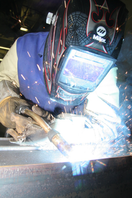 |
Fig. 7: The long neck on this 600-amp air-cooled Bernard Q™-Gun keeps a welding fabricator’s hands cooler, and it improves access into limited-access joints
|
As any supervisor knows, productivity also depends on operator comfort. To enhance operator comfort in this high-amperage welding application, Keller appreciates the fact that Bernard offers an air-cooled gun with a long neck (see Fig. 7).
“The longer neck keeps the heat away from the operators hand. They love it because it keeps them cooler,” he says. “In fact, with a competitor’s gun, they’d burn up welding gloves during testing.”
Full Production
ITEC approaches each manufacturing challenge with common sense: look at the entire process from front to back, examine each step and come up with new and innovative ways to streamline the process. This approach lets Keller and Grimes choose the exact equipment they need—from the power source to the wire and the Jump Liner—and integrate the entire process to optimize production flow and minimize operating costs.
“I’ve been in this industry for 45 years,” explains Keller. “I’ve seen how things go if you don’t plan everything ahead of time. You can’t shoot from your hip. You’ve got to plan it out and decide what’s going to work and how it’s going to work.”
The result of this foresight: an operation that has ramped up to full production in three short months.