Common TIG welding problems
Gas tungsten arc welding (GTAW), or TIG, is often specified to meet strict aesthetic, structural or code/standard requirements. The TIG process is complex, and it is undisputedly the most difficult process to learn. Follow these basic tips to prevent common TIG welding problems.
1. Poor gas coverage
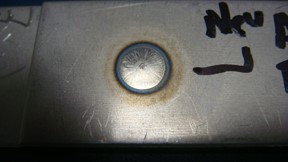
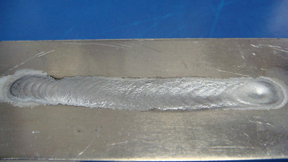
The weld here shows contamination caused by lack of shielding gas. This can happen when the shielding gas is not turned on, there is either too little or too much gas shielding, or the gas is blown away.
- To troubleshoot gas contamination issues, check the gas cylinder label to ensure you’re using the right type of gas for TIG welding. The most common is 100% argon (or perhaps an argon/helium blend for thick aluminum). Attempting to weld with an argon/carbon dioxide mix (commonly used for MIG welding) will cause immediate contamination.
- Set the proper gas flow rate, which should be 15 to 20 cubic feet per hour (cfh) for most applications. Welders commonly — and incorrectly — assume that a higher gas flow/pressure provides greater protection. In fact, excessive gas flow creates turbulence and swirling currents that pull in unwanted airborne contaminants. It can also cause arc wandering). Generally, err on the lower side of recommended shielding gas rates to ensure proper shielding coverage without turbulence.
- Check all the fittings and hoses for leaks. Any breach may pull air into the shielding gas stream, which can contaminate the cause the weld. Rub soapy water over the hose and all fittings. If bubbles form, you have a leak and need to replace the defective components.
- Assuming you have a full cylinder, the right gas and no leaks, you may have a tank contaminated with moisture. Shielding gas cylinder contamination does not happen frequently, but it is possible. Check with your gas supplier to resolve this issue.
Read more about TIG shielding gas best practices.
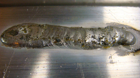 |
| Figure 1: Poor gas coverage leads to contamination. |
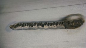
2. Welding aluminum in the wrong polarity/adjusting balance
This TIG weld (Figure 2A) was created with the machine’s polarity set on direct current electrode negative (DCEN). As you can see, the weld did not break down the aluminum oxide layer. The filler metal mixed in with the partially melted oxide, creating the contaminated bead seen here. To defeat this, always TIG weld aluminum with the polarity set to alternating current (AC).
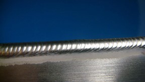
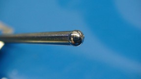
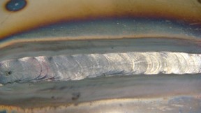
TIG welding in AC (Figure 2B) allows the electrode positive (EP) portion of the cycle to blast away the aluminum oxide while the electrode negative (EN) portion melts the base metal. A feature called AC balance control allows operators to tailor the EP to EN ratio. If you notice a brownish oxidation or flakes that look like black pepper in your weld puddle (Figure 2C), decrease the balance setting. This will increase the time in EP or the time spent in the “cleaning action." However, note that too much EP causes the tungsten to ball excessively (Figure 2D) and could provide too much etching. Lastly, when TIG welding aluminum, do not start welding until the puddle has the appearance of a shiny dot. This indicates that the oxide has been removed and it is safe to add filler and move forward. Adding filler to the weld zone before removing the oxide layer results in contamination.
|
|
Figure 2A: Aluminum welded in DC with argon
|
|
|
Figure 2B: Ideal aluminum weld
|
|
|
Figure 2C: AC balance set too high(insufficient oxide removal)
|
|
| Figure 2D: balled tungsten caused by a low balance setting (excess EP) |
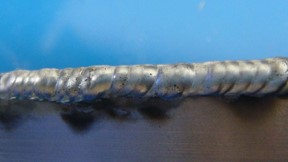
3. Weld graininess
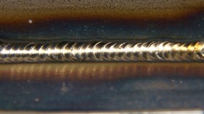
Figure 2B shows the way an aluminum TIG bead should look. Figure 3 shows a bead with a grainy appearance, which is typically due to filler metal problems. For instance, a 4043 aluminum filler rod from one manufacturer may have different properties than a 4043 rod from another manufacturer. The welder (if the application permits) may need to adjust filler brand accordingly. The rod may also be defective (too much of a certain ingredient). The welder may even have the wrong type of filler rod, such as 4043 filler instead of 5356 filler.
Prior to welding, always check the filler metal type and remove all grease, oil and moisture from the surface to prevent contamination.
|
Figure 3: Grainy aluminum weld
|
4. Lack of fusion in the root
A number of factors cause lack of fusion at the root of a T-joint or a fillet weld. These include improper fit-up, holding the torch too far away from the joint (increasing arc length) and improperly feeding the filler rod. This issue arises more often with a transformer-based machine — the arc tends to wander between the two sides of the joint as it seeks the path of least resistance. In this case, reducing arc length will provide better directional control and help increase penetration. It is also important not to under-fill the joint or weld too quickly to avoid this TIG welding problem.
Note that inverter-based machines with advanced output controls such as adjustable frequency and pulsing controls offer more control over the arc. These controls create a narrower, more focused arc cone, providing better directional control over the weld puddle and deeper penetration (and often at increased travel speeds).
|
Figure 4: Lack of fusion in the root
|
5. Craters
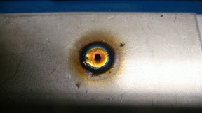
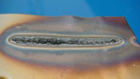
Craters, such as the one shown in Figure 5A, typically occur at the end of the weld, and they often lead to cracking. Causes include instantly reducing the welding power (which causes the puddle to cool too quickly) and removing the filler rod too quickly at the end of the weld. You can fix crater cracking issues by continuing to feed filler rod while slowly reducing current at the end of a weld. Some TIG welders feature a crater control function that automatically reduces the current at the end of a weld. The result is a good-looking weld bead, as seen in Figure 5B.
|
Figure 5A: Poorly filled weld craters
|
|
Figure 5B: Weld crater filled
|
6. Dirty base and/or filler metal
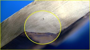
One of the first things you should have learned about welding is to clean materials prior to welding. This photo (Figure 6A) shows what happens when you don’t clean the mill scale off hot-rolled mild steel. Clean all base and filler metals, including mill scale, oxide on aluminum, or dirt and grease on filler metals. Grind, brush and wipe away all potential contaminants. For cleaning aluminum, dedicate a stainless steel brush to the task to prevent contamination from other metals.
Figure 6B shows what happens when a weld on mild steel has been properly cleaned before welding. Figure 6C shows a weld made on uncleaned chrome-moly tubing, while Figure 6D shows a weld made on clean material.
7. Poor color on stainless
Figure 7A shows discoloration on a stainless steel weld caused by overheating, which not only affects a material’s color but degrades its corrosion resistance and mechanical properties as well. Unfortunately, once this error is made, there is nothing that can be done to fix it. To prevent overheating, reduce amperage, slightly increase travel speed or shorten the arc length. If your welding equipment features pulsed welding capabilities, now is the time to learn how to use them. Pulsing reduces heat input, and it offers excellent control of the weld puddle. Figure 7B shows proper coloration of stainless.
|
Figure 7A: Poor color on stainless steel
|
|
| Figure 7B: Good color on stainless steel |
8. Sugaring on stainless steel
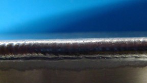
Figure 8 shows sugaring on the backside of a stainless steel weld, a common TIG welding problem. Sugaring (oxidation) occurs around the weld when it is exposed to oxygen in the air. The best way to prevent sugaring is to back purge the weld with argon shielding gas or reduce welding amperage.
|
Figure 8: Sugaring on stainless steel
|
9. Too much amperage on aluminum
Figure 9A shows what a weld bead looks like on aluminum with the amperage set too high. This creates a wider profile, an ill-defined bead and can potentially lead to burn-through. To solve this problem, reduce amperage and/or increase travel speed. Reference back to Figure 2B to identify an ideal weld.
 |
| Figure 9: Excessive amperage/heat input |
10. Proper arc length control
The color change in the middle of this aluminum weld bead (Figure 10) resulted from an increase in arc length. Arc length, which is the distance between the electrode and the base metal, determines TIG welding voltage. Holding too long of an arc increases overall heat input and the potential for distortion. It also widens the weld bead while decreasing penetration, and affects weld bead appearance. Practice holding a consistent arc length to improve heat input control and improve weld bead quality.

|
| Figure 10: Change in arc length |
This article originally appeared in The Fabricator Magazine and is shared with permission.