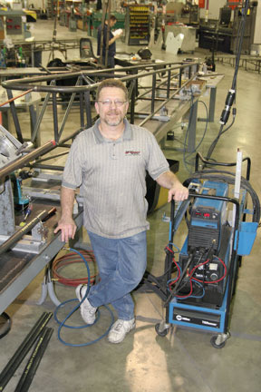
By Louie Contrerars, Owner, L-Con Race Cars, LLC
In the last installment of Project S3 "Rally" WRX we accomplished all the basics to get started in the dirt. The car has been very well prepared for rally-x events, so now it's time to take things to the next level and install a roll cage. There are many reasons to install a roll cage in a vehicle. The most obvious is for safety. The less obvious is the chassis strengthening that goes hand-in-hand with the installation of a proper race legal cage. There are a few points that need to be addressed immediately; a roll cage in a street-driven vehicle can do more harm than good. Most compact cars leave very little space for the cage tubes to run with any great distance from the vehicle's occupants, making the occupants very vulnerable without a helmet. The bottom line is, if you choose to do a full race cage, do it in a full race car.
Now that we have that out of the way, let's have a look at the cage project at hand. Steve Sawitz of Laguna Beach, Calif., decided it was time to retire his 03 WRX from his daily driver to his weekend play toy/rally car. Steve contacted L-Con Race Car Fabrication and Engineering in Placentia, Calif., about installing the Gravel Crew cage kit. The kit includes a 1.5-in. OD (outer diameter) with a .120-wall thickness DOM seamless tubing B-Pillar, 2 A-pillars and a windshield bar. As an option, a complete water jetted floor plate kit with attachment points of no less than 14 places for the '02 to current unibody shell (see Fig. 1) is also available and used here. The kit was designed to work for many race applications and features only four main points, leaving the decision to install additional tubes up to the customer and their racing organization's rules. This particular car will be built to run in CRS (California Rally Series) events. One of the main things that Steve stressed to L-Con was the importance of strengthening the vehicle, as he wants to jump, and jump big.
 |
| Fig. 1 |
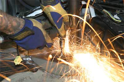
The project gets underway with the complete disassembly of the interior of the car, trunk and a good portion of the engine compartment. After the car's interior has been gutted, the car is prepared and further stripped of paint, primer and body sealant in all the places where tubes will eventually make contact (see Figures 2, 3 and 4).
The thickness of the body shell alone cannot take the pressure of the end of a 1.5-in. tube with all of the vehicle's weight on it, so there are plates installed to spread the load should a car get upside down (see Figures 5 and 6).
Fig. 5 |
Fig. 6 |
Once the body shell has been cleaned in the necessary areas, a few holes must be drilled in the body shell for later steps (see Figures 7 and 8).
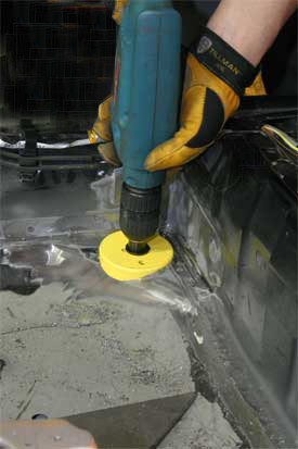
Fig. 7 |
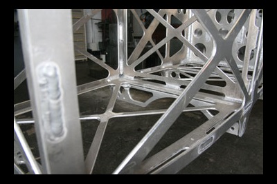
Fig. 8 |
First 2-3-in. holes must be drilled under the plate locations for the B-pillar. Then 1.5-in. holes are drilled in the far outside of the firewall on both sides. This makes a provision for the tubes that will secure the front suspension to the interior roll cage.
L-Con tack welded plates on the frame rail in front of the strut towers, on the front, top and rear of the front towers, at the base of the Subaru's A-pillars, base of the B-pillar, and front, top and inside of the rear strut towers (see Figures 9, 10 and 11).
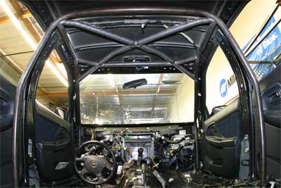
The next step was to fit and tack weld the 4 main points of the cage in place (see Fig. 12). Two 1.5-inch .120 tube gussets are installed from the front of the windshield bar to the middle bend on the A-pillar (see Fig. 13).
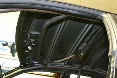
Fig. 12 |
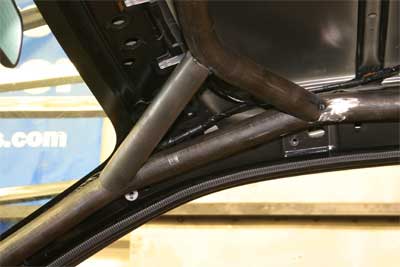
Fig. 13
|
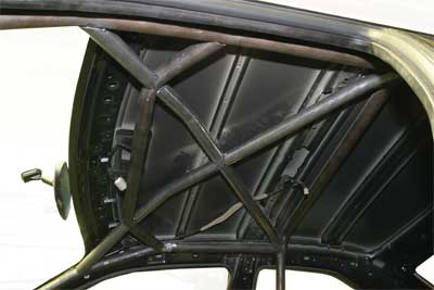
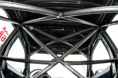
Next an "X" formed with two tubes is fitted on the roof plane (see Fig. 14).
 |
| Fig. 14 |
The front of the X is fitted to the back of the windshield bar, tubes aligning with the A-pillar gussets. Finally, two tubes are slightly bent and installed from the lower bends of the A-pillar through the firewall and are fitted to the plate on the back of the front strut towers (see Figures 15 and 16).

Fig. 15 |

Fig. 16 |
Once the whole structure is tacked and in place, the entire structure is welded as much as possible where it sits. Then the tack welds at the bottom of the B-pillar and its plates are cut with a die grinder (see Fig. 17).
 |
| Fig. 17 |
The plates are then removed, exposing the 3-in. holes that were drilled earlier in the process (see Fig. 18). The holes are now right below the bottoms of the B-pillar.
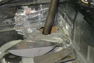 |
| Fig. 18 |
This makes it possible to drop the rear of the cage through the floor of the car at least 12 inches (see Fig. 19).
 |
| Fig. 19 |
This gives L-Con access to the top and outside edges of the roll cage structure for welding (see Fig. 20).
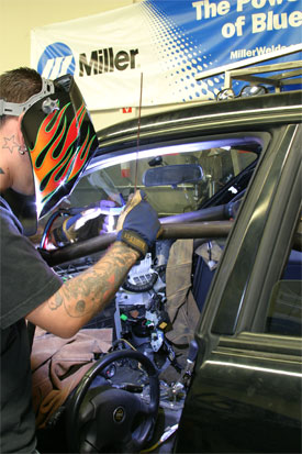
Fig. 20 |
The remaining un-welded joints are welded while it is through the floor. The cage is then raised up through the floor and tack welded back in place with the floor plates (see Fig. 21).
 |
| Fig. 21 |
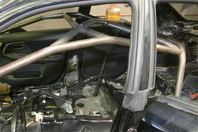
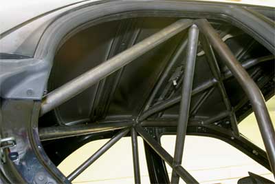
Approximately 30 feet of 1.5-inch .120 and 24 feet of 1.5-inch .095 DOM tubing are on hand to complete the structure. An X is installed on the B-pillar, with two lateral connecting tubes for the shoulder harnesses (see Fig. 22).
 |
| Fig. 22 |
Two more tubes are installed to join the B-pillar and the plates fixed to the front face of the rear strut towers (see Fig. 23).
 |
| Fig. 23 |
A single tube joins the 2 strut towers via plates welded down the inside. An X is installed on the B-pillar to strut tower plane, offering a tremendous amount of strength to the entire chassis (see Fig. 24).
 |
| Fig. 24 |
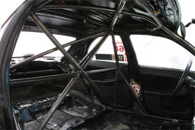
One of the major things to consider when installing a roll cage is the effect it can have on the handling and overall structural integrity of the chassis. For instance, when the front and rear suspension pick up points are tied together by the cage structure, the cage acts as a sway bar which dramatically cuts chassis twist, and body roll (see Fig. 25).
 |
| Fig. 25 |
The potential problem occurs over time as the car is driven to its limit and twists to the point where the mounting surfaces of the cage are compromised-making it useless in a hard accident. The best way to avoid this problem (especially for rally cars) is to connect the cage structure to the body shell in as many places as possible (see Figures 26, 27 and 28).
L-Con has fabricated custom sheet metal plates, which get drilled then dimple died for weight and strength, and then are installed everywhere the cage comes into contact with the shell. The plates are imperative to tie all major points of the cage to major points of the car's chassis. Without plates attaching the upper half of the cage to the chassis, the cage would flex as much as 3/8 of an inch under hard driving! The end result of installing a high quality roll cage is a whole new car-a car that will perform and last with some proper and effective suspension tuning. Look for Steve flying down a dirt road or launching his rally car in random industrial parks.
Tools Required:
o Safety glasses, welding gloves, leather work gloves
o Millermatic 350P MIG welder and a Syncrowave 350LX TIG welder
o 1.5-inch DOM .120 WRX main hoop, A-pillar bars, upper window bar, and .125 mild steel floor plate kit (www.l-con.net)
o Crud thug, 90-degree grinder (www.snap-on.com)
o 10mm, 12mm, 14mm sockets
o Screwdriver set
o Tamper-proof 8mm Torx driver
o 1-2-inch collet and 1 box of blue roll lock, cut off wheels with cole, 3.5-in. flap wheels, 3-in. and 1.75-in. hole saw and chuck (available at industrial hardware stores)
o Metal cutting chop saw
o Electric grinder
o Tubing notcher
o Drill
o 80 feet 1.5-inch .120 DOM, 40 feet 1.5-inch .095 DOM (available at local metal supply)
o 3 lbs. 3/32 70s2, 2 lbs 3/32 silica bronze welding rod
o 20 lbs. dry ice (welding supply store)