Tips to Improve TIG Arc Starts and Promote Arc Performance in Aerospace and other Low Amp Applications
Print Article
Miller's Blue Lightning enables aerospace and other TIG welders to eliminate the root cause of many rejected welds while positively and consistently starting a DC TIG arc at 1 amp. This article provides tips on how to improve low-amp TIG starts.
As welders familiar with AWS D17.1 and other codes for aerospace applications know, TIG welding (GTAW) requires the use of non-contact or high frequency arc initiation techniques to eliminate a potential source of inclusions in the weld bead.
High frequency (HF) provides a path of least resistance for the welding current to follow. However, in conditions where the arc fails to positively initiate, the HF current sometimes "dances" around the weldment, producing uncontrolled arc start marks on the workpiece, which then must be rejected. Uncontrolled arc starting conditions may also cause a burst of weld current that burns through thin metal or melts the knife-edge of small parts.
To combat these issues, aerospace welders often use a "run-on tab" (a small block of brass or other metal) on which to start the arc and then carry it over to the workpiece. While solving problems, a run-on tab doesn't eliminate the root cause of rejected welds, nor can it be used in all situations.
Fortunately, Miller's new Blue Lightning technology now enables aerospace welders to eliminate the root cause of many rejected welds while positively and consistently starting a DC TIG arc at 1 amp. In addition, the thousands of TIG arc start tests conducted during the R&D phase of technology development produced new insights into conditions that promote better arc starts and weld quality. This article provides new insights into improving DC TIG arc starts and reinforces the importance of some existing best practices for aerospace welding.
|
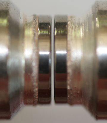
Fig. 1: Point Gap Problems. Traditional TIG machines feature a set of HF arc starting points that function in a manner similar to a spark plug gap. Any variability (such as grinding dust, dirt or high humidity) changes the amount of resistance required to bridge the gap. Inverter technology better managed this variable, but it didn't eliminate the source of erratic arc starts
|
|
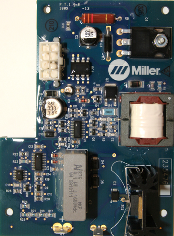
Fig. 2 Consistent Capacitors. The newest inverters, such as Miller's Dynasty and Maxstar inverters, designed for aerospace welding, tool/die welding and other low amperage TIG applications, feature Blue LIghtning technology that functions much like a capacitor with an output controlled by a high-speed power switching transistor. This circuit provides more consistent HF arc starts because it eliminates sources of variability.
|
|
|
|
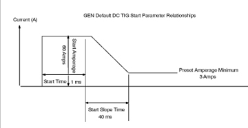
Fig. 3 More Variables Controlled. Old DC TIG arc starting technology controlled one variable: amperage. Blue LIghtning technology technology controls four variables: amperage, time at amperage, slope time and minimum amperage. More control eliminates the current over-shoots that cause burn-through.
|
|
|
|
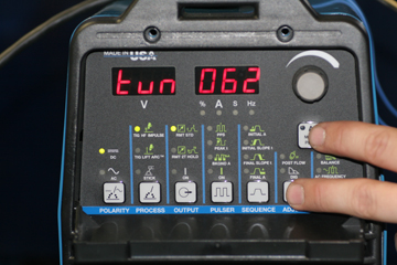
Fig. 4 Automatic Simplicity. Obtaining consistent arc starts with Blue LIghtning technology technology is as simple as selecting the size of the tungsten you're using from a built-in menu. A "general" category allows users to create a custom program for unique applications, such as unusually long weld cables with increased resistance.
|
|
|
|
Fig. 5 Shun Cheap Tungstens. No welding machine in the world can compensate for the poor arc starts and erratic arc created by tungstens with a poor grain structure. This problem, often caused by improper annealing, manifests itself when the tungsten bends and/or shatters instead of breaking cleanly.
|
|
|
|
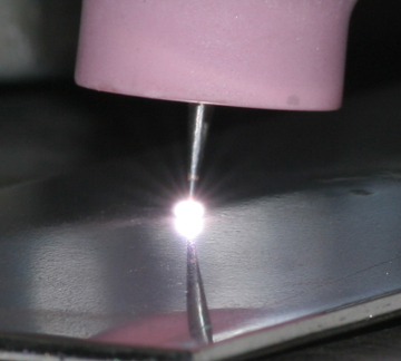
Fig. 6 Pay for Performance. Quality tungstens, such as those from Weldcraft, Diamond Ground and Sylvania, promote smoother electron flow and better arc starts because they have a fine, evenly distributed grain structure and evenly distributed doping elements (e.g., Lanthanum).
|
|
|
|
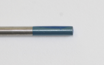
Fig. 7 2% Lanthanated for DC TIG. Use a 2% Lanthanated tungsten (AWS EWLa-2, as indicated by the blue band) for welding stainless steel, Inconel®, nickel and cobalt alloys, titanium and most other aerospace alloys. Lanthanated tungstens provide excellent arc starting and current carrying capabilities, are non-radioactive and can deliver up to 200 arc starts without significant tip erosion (vs. 70 arc starts for 2% Thoriated).
|
|
|
|
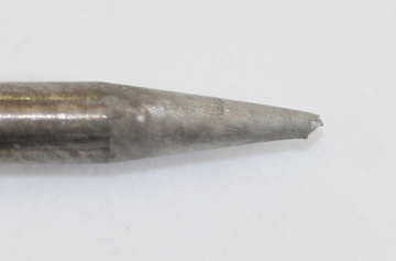
Fig. 8 Avoid a Frosted Tungsten. After a few dozen arc starts, tungsten forms a "frost," as shown here. This frost insulates the tungsten and degrades arc starts, so redress the tungsten as often as necessary.
|
|
|
|
Fig. 9 One Acceptable Method. Whenever the tungsten becomes contaminated, the only acceptable method of removing the contaminated portion is using a high-speed cut-off wheel (vs. the "garage" practice of snapping off the tungsten end on a table edge, which can lead to splintering and cracking).
|
|
|
|
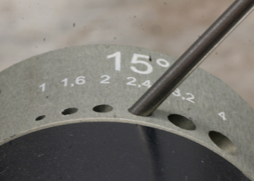
Fig. 10 Grind with the Grain. Use a special tungsten sharpener that grinds the tungsten longitudinally (which promotes current flow) and eliminates any rough spots that could interrupt smooth current flow.
|
|
|
|
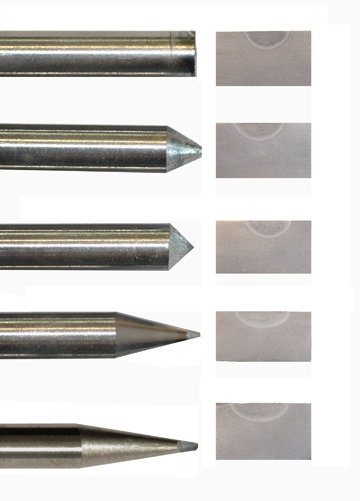
Fig. 11 The Impact of Point Angles. Contrary to popular belief, a pointed tungsten does NOT provide deeper penetration (but it DOES provide better directional control). The reason is that current comes the tungsten perpendicular to the grind angle. As these images show, use a longer taper for shallower penetration and a blunter taper for deeper penetration.
|
|
|
|
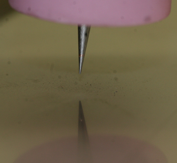
Fig. 12 Pointed Tungsten for Low Amperage. Sharply pointed tungstens reduce resistance and improve arc starts in low amperage applications. In applications above 20 or 25 amps, consider putting a very small land on the end of the point to prevent it from melting and becoming included in the weld puddle.
|
|
|
|
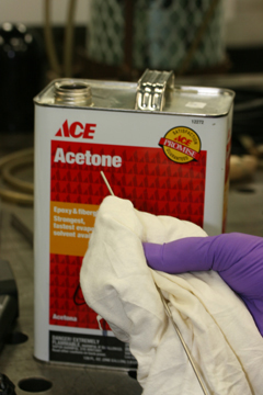
Fig. 13 Avoid Oils. The oil from your fingers can affect arc starts and lead to weld contamination, most notably with titanium. For critical applications, wear nitrile gloves when handling the tungsten and filler wire, and clean these items with acetone prior to welding.
|
|
|
|
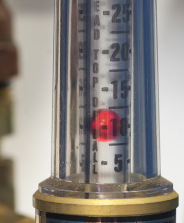
Fig. 14 Back Off the Gas. For welding at 10 amps or less, reduce gas flow from 15 to 12 cfh to prevent the gas flow from extinguishing the arc.
|
|
|
|
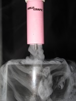 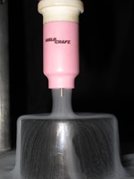
Fig. 15 Go with the Flow. Using a gas lens (right) smoothes gas flow and promotes better gas coverage. Without a gas lens (left), the gas flow becomes turbulent. The swirling current could pull in atmospheric contaminants.
|
|
|
|
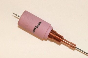
Fig. 16 Pay Attention to Consumables. Cups, collets and collet bodies don't last forever. Worn cups can cause gas turbulence, while worn collets and collet bodies create excess resistance and provide poor conductivity, leading to hot spots on the torch and poor arc starts.
|
|
|
Control the Variables
As this article has shown, promoting consistent and positive arc starts and maintaining arc stability depends upon eliminating and controlling every variable possible. The old adage, "prior planning prevents poor performance" certainly comes to mind. Manufacturers of TIG inverters for aerospace applications are working hard to control machine-related variables for the arc starts and low-end arc performance critical to aerospace welding. When welders work equally as hard to manage the variables within their control, they can be confident that better arc starts and arc performance will follow.